
Descripción
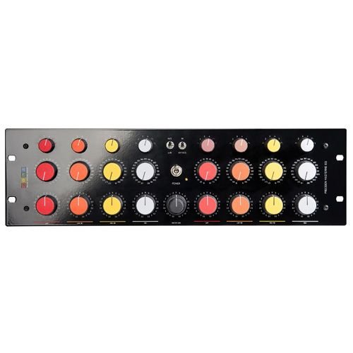
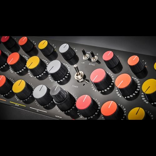
New face plate design to accommodate a wider range of customers based on feedback (can swap caps to black to tone down colours)
The Circuit
…is pretty self explanatory. 2 x 4 bands of EQ with switchable HPF/LPF on the low and high end, wrapped around an MS matrix, and a master gain.
The Philosophy
Based on the highly regarded “NetEQ”, by the late Barry Porter. After many years of listening tinkering with the design, building, and listening, and adjusting, and listening, and doing custom units with various solutions — and listening — the only thing that remains unchanged is the parallel filter section. The in- and output sections, the high and low pass filters, the layout of the circuit, the Q circuit, and the whole implementation of it has been redesigned, and when the listening tests were done, I took a really deep dive into the details and precision of all the controls.What I have arrived at, is a very personal iteration of the circuit, with a new level of refinement. Still a Porter at its core, but also, very much a Grinder.
-
2 x 4 band equalizer
-
Six Q settings per mid band, five Q settings per low/high band
-
Shelving mode on high and low bands (switchable on the Q)
-
L-R/M-S switchable interface
-
Global bypass
-
23 step Blore-Edwards switches for gain and Frequency control
-
Gain of 0.5dB steps and a max of 5.5dB cut or boost per band
-
Split L-R/M-S master gain
-
Matched to better than 1% relative tolerance
-
Modern, precision in- & output section
- The Circuit
…is pretty self explanatory.
2 x 4 bands of EQ with switchable HPF/LPF on the low and high end, wrapped around an MS matrix, and a master gain.
The Philosophy
Based on the highly regarded “NetEQ”, by the late Barry Porter.
After many years of listening tinkering with the design, building, and listening, and adjusting, and listening, and doing custom units with various solutions — and listening — the only thing that remains unchanged is the parallel filter section.
The in- and output sections, the high and low pass filters, the layout of the circuit, the Q circuit, and the whole
implementation of it has been redesigned, and when the listening tests were done, I took a really deep dive into the details and precision of all the controls.
What I have arrived at, is a very personal iteration of the circuit, with a new level of refinement. Still a Porter at its core, but also, very much a Grinder. - Frequency Selection
23 frequency steps for each band, matched to 1% or better, Blore Edwards Switches.
Gain +/-5.5dB total gain per band, as well as +/.5.5dB of total gain on the dual concentric master gain, all in steps of 0.5dB, Blore Edwards Switches.
Q
The Q was changed from RMS to peak gain behaviour.
RMS behaviour keeps the energy constant, while the peak behaviour keeps the peak level constant.
Think of a balloon, if you squeeze it to make it narrower, it gets longer (higher peak, same amount of energy), but if you let a little air out, it will stay the same height as before (static peak, less energy).
What is preferable comes down to temperament, but aside from the practical aspects, I found that the redesigns
gave a less ringy and more intuitive behaviour, especially at more narrow settings. - High & Low Pass Filters
In the original design, the high and low pass filters were added in series with the core circuit, and they were done with a simple RC filter on an opamp.
I always found them to be a bit “out of place”, when I switched them in, with the bands standing out relative to the rest of the EQ, so I nixed Porter’s HP/LP add-on, and with the help of a few relays, I tapped directly into the core ofthe parallel circuits.
The resonance peaks on them don’t look very good on paper, but they sound amazing, and they are fully
sympathetic to the other bands, when they are in action.
MS
Ms circuit, built on modern, precise, integrated circuits.
Center Section
● Bypass, bypasses the filter section
● MS, wraps the MS encoder and decoder around the whole filter circuit.